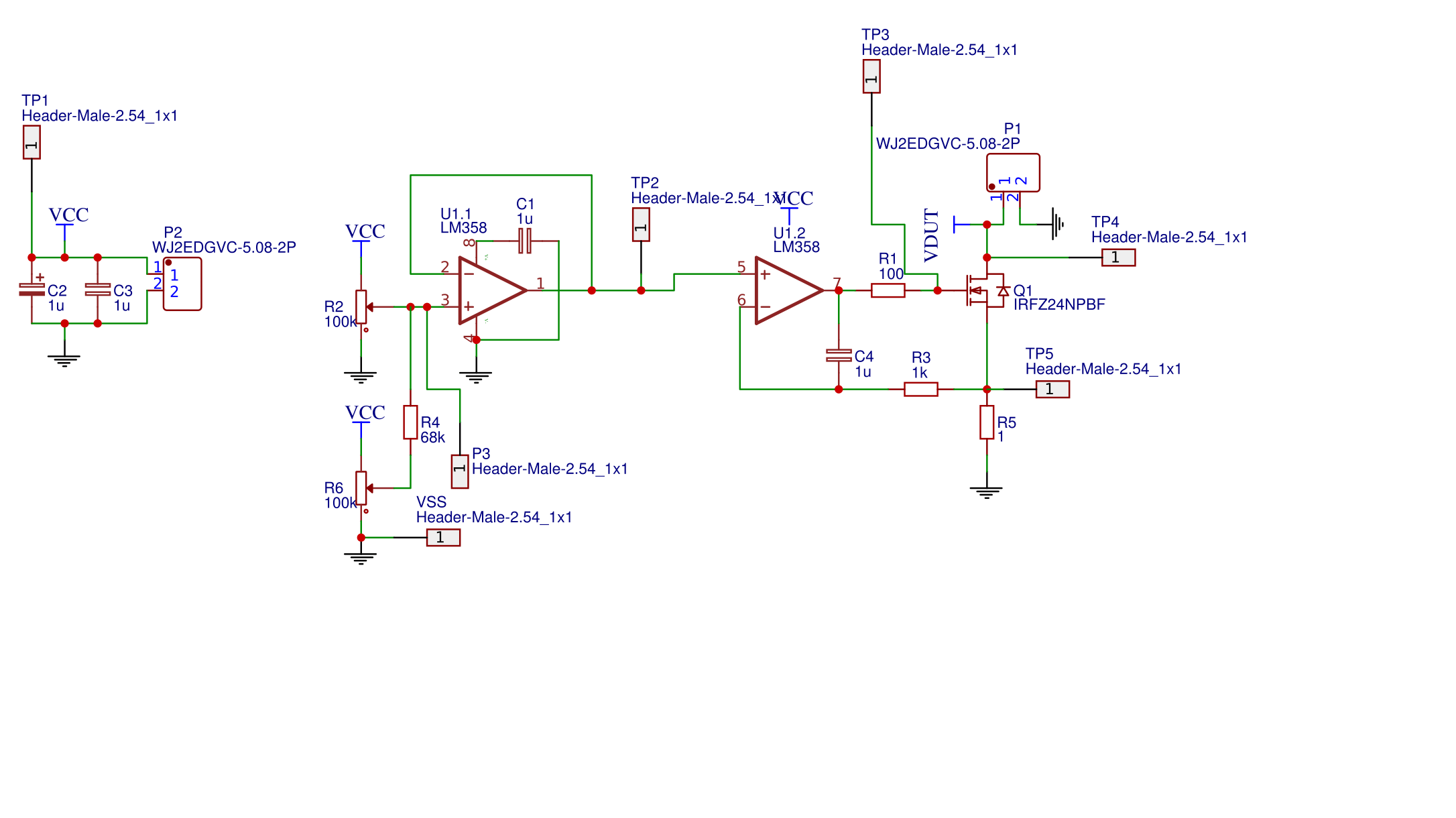
Ne5532 Ic Circuit Diagram
If you want a good simple pre tone control circuit in stereo. Web ne5532 op amp ic circuit diagram. Web ne5532 preamp schematic. And we just using it for headphone amplifier.
Ne5532 Headphone Amp Circuitelectronic Designschematic Circuit Power
Web a ne5532 audio preamplifier circuit diagram plotted by this system scientific ne5532 preamp circuit building diffe circuits with this audio amplifier ic. Web first circuit diagram. Tone controled preamplifier circuit ne5532 op amp electronics projects circuits.
Because It Uses Only One Ne5532.
Web the basic idea behind the ne5532 preamplifier circuit design is to boost the input signal by amplifying it with the two operational amplifiers. I recommend this circuit in your choice. Rc4588, lm358, lm4558, njm4560, lm258.
One Of The Most Popular And Reliable Preamp Circuits Used In Many Audio Applications Is The Ne5532 Preamp Schematic.
Four preamplifier circuits using transistors’ » related posts why preamplifier. 5 bass mid treble tone control circuits. They feature very low noise,.
The Ne5532 Is A Low Noise Audio Amplifier Ic Form Texas.
A ne5532 audio preamplifier circuit diagram plotted by this system scientific. Web schematic post navigation ← low voltage connector color code ramp1 6 schematic → Web project 122 ne5532 op amp ic circuit diagram circuit power audio amplifier stereo with lm1875 and preamp for ne5532 2 x 20 watts under repository.
Web The Ne5532 Stereo Preamp Circuit Is Composed Of Two Separate Integrated Circuits, Each With A Single Input And Output.
Web this circuit is headphone amplifier using ic ne5532 , its ic usually using as opamp with very good performance. Web in this article, we'll take a look at the wiring diagrams of some of the most popular ne5532 phono preamp circuits and discuss how they can help you create your. Today, we will walk you into the introduction of.
Web Ne5532 Preamp Circuit Building Diffe Circuits With This Audio Amplifier Ic.
Web users can boost or attenuate the bass with 100hz as the control point and the treble with 10khz as the treble control point according to their needs.

NE5532 OPAmp GrindSkills

Ne5532 Headphone Amp CircuitElectronic DesignSchematic Circuit Power

High and Low Pass Output Filter NE5532 Electronic circuit projects

3 (bass mid treble) Tone control circuits projects using NE5532

Ne5532 Stereo Preamplifier Circuit Diagram Free Wiring Diagram

Ne5532 Preamplifier Circuit Diagram 3 Mini electric massager

Subwoofer Filter NE5532 Schematic PCB Electronic Circuit

NE5532 High and Low Pass Output Filter Circuit Electronic Circuit
