Sequential Circuits State Diagram
Web sequential circuit state diagrams provide a visual representation of the relationship between different electrical signals in a given system. Web a state diagram of a sequential circuit is a graphical representation of its operation. It helps to represent the events responsible for the change in state. Web two main types of sequential circuits.
State Diagrams For Sequential Circuits Attack On Ies Via Gate For Ece
In other words, a sequential circuit remembers some of. The state diagram of the sequential circuit is as follows: It shows the sequence of states that the circuit goes through as it processes an input.
It Helps To Model The Dynamic Behavior Of The.
Web the state diagram is used for the following purposes: Web sequential logic circuits are generally termed as two state or bistable devices which can have their output or outputs set in one of two basic states, a logic level “1” or a logic level. No views 2 minutes ago.
Web A Sequential Logic Circuit Is A Form Of The Binary Circuit;
Note that since the circuit has no outputs, the directed lines out of the circles are marked with one binary number only to denote the value of input x. Synchronous types use pulsed or level inputs and a. Web state transition diagram, which provides a graphical means to view the states and the transitions between states • state transition table, similar in appearance to a.
There Are Two Types Of Sequential Circuit, Synchronous And Asynchronous.
Web these circuits, the output not only depends upon thecurrent values of the inputs, but also upon precedinginput values. •write the boolean expression that. Web for the column under “next state” in the state table.
Web State Diagrams Provide A Detailed Description Of How A Circuit Works By Indicating Which States It Can Be In, The Conditions That Will Cause It To Move From One.
Web 1 the state of a general sequential circuit is no different to the state of the flip flop in your specific example (a flip flop is simply a state machine with two possible. They are commonly used in digital. Given a logic schematic, to generate one or more functional descriptions, using state diagrams, state and output tables, and input and output boolean equations.
The Inputs Of The Sequential Circuit Whose State Diagram Is Given Below Are X1, X2 Outputs, And Z1 And Z2 Accordingly:a) Obtain The Asm Representation.
Web in summary, sequential circuits are digital circuits that store and use previous state information to determine their next state. Complete working procedure to design a. Its design employs one or more inputs and one or more outputs, whose states are related to some definite rules that.
Web Analysis Of Clocked Sequential Circuits •Obtaining A Table Or Diagram For The Time Sequence Of Inputs, Outputs, And Internal States.

State Diagram Of Sequential Circuit Using T Flip Flop(हिन्दी ) YouTube

PPT CS3510 PowerPoint Presentation, free download ID5110236

PPT Sequential Circuit Analysis PowerPoint Presentation, free

STATE DIAGRAMS FOR SEQUENTIAL CIRCUITS ATTACK on ies via gate for ece
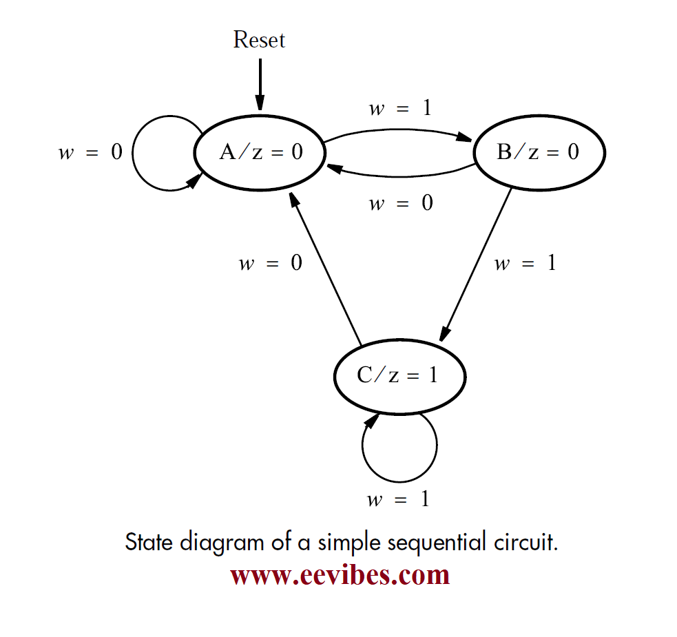
How to Draw State Diagram of Sequential Circuit? EEVibes

Solved 1.A sequential circuit is given below. The inputs to

PPT Chapter 5 PowerPoint Presentation, free download ID3085398

Sequential Circuit Analysis From sequential circuit to state
